Some Studies on Cutting Force Generation in Machining of Mg-Ca1.0 Alloy
Ketan Jagtap* and Suresh Sanap
Department of Mechanical Engineering, Government Polytechnic Nashik, Maharashtra, India
E-mail: ketanjagtap@gmail.com; sanapsd@gmail.com
*Corresponding Author
Received 14 March 2024; Accepted 31 March 2024; Publication 13 April 2024
Abstract
Magnesium alloy has qualities that are similar to those of bone, it is now commonly acknowledged as a biodegradable material. Mg-Ca1.0 is a recently developed biodegradable substance that doesn’t cause any harmful substances to be produced in the body. It is frequently utilized in fixation screws and supporting plates for bone implants. To far, very little research has been published on the machining of biodegradable Magnesium Calcium alloy. This investigation’s goal is to evaluate the cutting forces produced during a face milling procedure. The experimental work used a one-factor-at-a-time strategy to assess how process factors affect performance attributes. The current study uses a CVD diamond-coated insert to examine how the depth of cut, feed rate, and cutting speed affect the radial (F), tangential (F), and axial (F) cutting forces during face milling in a dry machining environment.
Keywords: Face milling, Mg-Ca1.0 alloy, cutting forces, one-factor-at-a-time, diamond coated insert.
1 Introduction
The need for lightweight structural components for the automotive, aerospace, transportation, and industrial automation industries has led to a rise in magnesium alloy manufacturing worldwide. One of the primary factors contributing to the growing use of magnesium alloys in computer covers, cell phone covers, video camera covers, consumer electronics, household appliances, etc. is their low weight (low specific gravity). In addition to these uses, magnesium alloys have recently been shown to be biodegradable materials in medicine that have the potential to reabsorb within the body. Humans will most certainly have severe issues throughout their lives as a result of age, illnesses, and accidents. Artificial bio-implants must be used to replace or alter the body’s natural orthopaedic joints. In the past, doctors had very few tangible options when it came to treating various medical issues.
Man-made materials known as biomaterials have the ability to perform the functions of human bodily tissues [1]. Biomaterials play a major role in treating patients by replacing or restoring the function of failing tissues or organs in medical devices like pacemakers and biosensors, as well as implants like vascular grafts, artificial hearts, heart valves, intraocular lenses, dental implants, and bone plates. The weakness of these current metallic biomaterials is the possibility of dangerous metallic ions and particles being released as a result of corrosion or wear processes, which reduces biocompatibility and causes tissue loss. Consequently, more study is needed to create a novel biomaterial.
Because the characteristics of magnesium-based alloys are almost the same as those of bone, they have drawn a lot of interest. Polymers like poly-L-lactic acid are the primary components of biodegradable implants. Unfortunately, the lack of mechanical strength in these polymer-based implants results in a low load-bearing capability. With a mechanical strength double that of biopolymers, magnesium and its alloys have a significant advantage over the latter. Research has revealed that magnesium-calcium alloys can be used as biodegradable materials in medical implants. While the elastic modulus (41–45 GPa) is similar to that of bone, magnesium has a higher fracture toughness than ceramic biomaterials, preventing the stress shielding effect.
The review of the literature reveals that various magnesium alloys have been the subject of studies. The characteristics of the biodegradable Mg-Ca1.0 alloy and the impact of various machining parameters have, however, received little attention from researchers. It has been noted that a number of factors, including the cutting tool, work material, cutting environment, and machining parameters, can affect the subsurface characteristics, microstructure, and surface finish of a machined surface. When machining biomedical implants, surface condition, mechanical and physical attributes, and other factors are critical factors to consider. Additionally, characteristics like residual stress, surface finish, microhardness, and microstructure have drawn a lot of attention in the past because they have a direct impact on the implant’s strength and degradation pattern. The surface quality of Mg-Ca bio implant alloys is significantly influenced by the cutting forces produced during machining. The cutting force generation pattern and magnitude have a significant impact on the surface integrity of bio implant alloys as well as plastic deformation. A few writers have previously shown how process parameters affect the cutting forces, as listed below.
Jagtap et al. investigated face turning in a dry cutting environment with a CBN insert and cutting settings of V 100–125–150 m/min, a 0.1–0.2–0.3 mm, and f 0.1–0.15–0.2 mm/rev [2–8]. Turning experiments were performed on AZ91HP magnesium alloy by Tönsoff et al. [9]. The author discovered that when cutting at higher speeds, the adherence of the workpiece material to the cutting tool increases the cutting edge radius, which in turn increases the machining forces. Cutting forces increase due to BUE formation at high cutting feed and depth of cut. Experiments on high-speed end milling on AZ91 magnesium alloy were carried out by Fang et al. [10]. The temperature of the cutting tool’s flank face, which ignites chips – was examined by the author. The maximum temperature measured at a cutting speed of 816 m/min and an undeformed chip thickness of 9 m is 302C, which is below the melting point of the magnesium alloy. The face milling of hybrid materials based on magnesium under dry conditions was studied by Ozsváth et al., who concluded that the AZ91–AlSi12 hybrid magnesium alloy is best suited for CVD diamond coated inserts [11]. Using a PCD-tipped tool, Salahshoor et al. investigated dry high-speed face milling of MgCa0.8 alloy [12]. They also adjusted the cutting depth (a 0.1–0.5 mm), feed rate (f 0.05–0.4 mm/rev), and speed (V 1200–2800 m/min) during the experiment. The feedrate has been found to have a considerable impact on surface roughness, increasing it from 0.2 m to 0.75 m. In contrast to the as-cast Mg-1Y alloy, rolling increases strength and reduces elongation, according to Xuenan et al.’s investigation of the Mg-1%Y alloy in both as cast and rolled conditions [13]. The authors also noted that Mg-1Y showed no appreciable toxicity to osteoblasts and could be taken into consideration when designing biomedical alloys. Y was found to have a detrimental effect on the corrosion properties of magnesium. Zhou et al. reported tensile ductility of up to 33% after studying the room temperature mechanical properties of as-extruded Mg-3%Y (extruded at 350C) [14]. Zheng et al.’s study examined the impact of thermo-mechanical treatment on Mg-6Gd-2Nd-0.5Zr [15]. They found that increasing cold deformation from 5% to 10% sped up the alloy’s age hardening response and increased strength. In their investigation of the Mg-10Gd-3Y-0.5Zr, Xiao et al. found that the Friction Stir processing (FSP) improved the ductility by dissolving the eutectic Mg5 (Gd,Y) and refining the grains [16]. The improvement in the strengths was the result of aging treatments administered after the FSP. Similarly, Li et al.’s study of the effects of FSP on WE43 alloy found that the microstructure of the alloy’s refined grains is what improves its mechanical properties [17].
Using carbide inserts, Hou et al. carried out a face milling operation on the magnesium alloys AM50A and AZ91D [18]. According to their findings, the formation of BUE at higher cutting speeds can lead to dimensional instability and vibration during machining, as well as an increase in surface roughness because of thermal expansion. In an experimental study, Kim et al. used pressurized air as coolant and a carbide cutting tool to face mill AZ31B magnesium alloy [19]. They varied the cutting speed (V 116–311 m/min), feed rate (f 0.04–0.25 mm/tooth), and number of inserts (n 1–6) while maintaining a constant depth of cut and analyzing the output variables. The author noticed that when the number of cutting inserts is changed, the surface roughness changes significantly.
2 Details of Experiment
2.1 Tool and Work Material
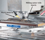
The Mg-Ca1.0 alloy plate used as the workpiece material which is forged to increase its strength and resistance to corrosion. The workpiece material’s chemical composition is as follows: 0.22% Cu-Al-Zn-Cr, 1% Ca, and 96.78% Mg. The insert, manufactured by Mitsubishi Hitachi make Japan, is a CVD diamond carbon coated carbide insert with specification SEET13T3AGFN-S SD5010, and it is clamped using a face milling tool holder called AFE45-4050R-4. For experimental work, a high-speed precision CNC HASS milling machine (Manufacture Hass Automation Inc., USA) has been used, featuring a 5.6 KW capacity and a maximum spindle speed of 4000 rpm (See Figure 1).
2.2 Methodology, Procedure and Measurement
An approach of one factor at a time is selected to carry out the experiment. With the input parameters displayed in Figure 1 and Table 1, all of the experiments were carried out in a dry machining environment as an environmental care.
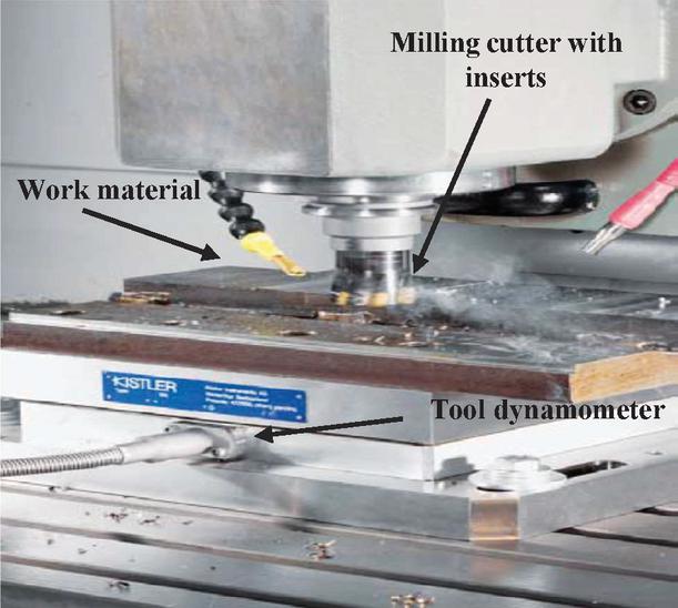
Figure 1 Actual Photograph of Face Milling of Mg-Ca 1.0 alloy.
Table 1 Input parameters and their values in relation to the cutting force results in Mg-Ca1.0 alloy face milling
| Expt. | Cutting Speed | Feed | DOC | Cutting Forces (max) (Newton) | ||
| No. | (mm/min) | (mm/rev) | (mm) | Radial (F) | Tangential (F) | Aial (F) |
| 1 | 300 | 0.3 | 0.3 | 21.86 | 21.06 | 54.32 |
| 2 | 375 | 0.3 | 0.3 | 11.69 | 16.24 | 10.44 |
| 3 | 450 | 0.3 | 0.3 | 11.02 | 17.7 | 17.15 |
| 4 | 525 | 0.3 | 0.3 | 9.705 | 17.4 | 15.93 |
| 5 | 600 | 0.3 | 0.3 | 10.28 | 17.79 | 18.25 |
| 6 | 600 | 0.1 | 0.3 | 2.93 | 2.197 | 5.188 |
| 7 | 600 | 0.2 | 0.3 | 28.69 | 21.67 | 49.44 |
| 8 | 600 | 0.3 | 0.3 | 2.96 | 2.258 | 5.066 |
| 9 | 600 | 0.4 | 0.3 | 2.93 | 2.228 | 4.944 |
| 10 | 600 | 0.5 | 0.3 | 3.357 | 2.747 | 4.944 |
| 11 | 600 | 0.3 | 0.1 | 2.838 | 2.167 | 4.944 |
| 12 | 600 | 0.3 | 0.2 | 2.869 | 2.197 | 5.009 |
| 13 | 600 | 0.3 | 0.3 | 3.021 | 2.563 | 5.798 |
| 14 | 600 | 0.3 | 0.4 | 2.93 | 2.197 | 5.005 |
| 15 | 600 | 0.3 | 0.5 | 3.326 | 2.899 | 6.348 |
A CNC milling machine and dynamometer (KISTLER Model 9257A, made in Switzerland) have been used to measure all cutting forces as shown in Figure 1. A three-component sensor is made up of two shear quartz (for F and F) and one pressure quartz (for F) integrated into a single casing. Four of these three-component sensors are installed in parallel between a base plate and a top plate under high preload. Multi-component force and moment measurements are also possible thanks to the dynamometer’s interconnection of the four integrated force sensor outputs.
3 Results and Discussion
The cutting forces, or F, F, and F, were noted as in-process response variables during face milling trials to conduct further analysis. Table 1 displays the values of the three measured cutting forces. The analysis is done to find out how the Mg-Ca1.0 alloy performs in relation to the machining parameters.
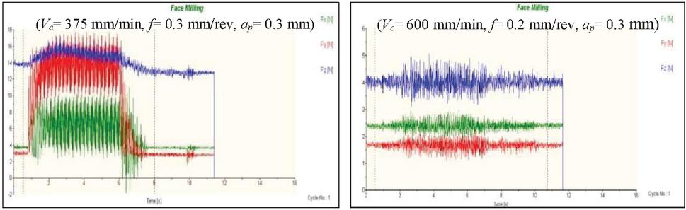
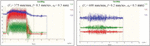
Figure 2 Real time cutting force signals during face milling of Mg-Ca1.0 alloy.
Based on the results analysis, this part determines and describes the process parameters that have a substantial impact on the variables. The cutting forces recorded in real time during the face milling of Mg-Ca1.0 alloy are displayed in Figure 2.
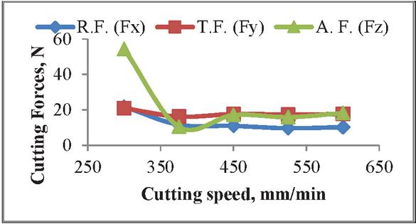
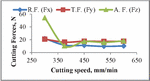
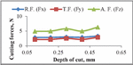
Figure 3 Cutting forces as a function of cutting speed.
3.1 Impact on Cutting Forces by Cutting Speed
Initially, the feed and cut depth were kept at 30 mm/rev and 0.3 mm, respectively, while the cutting speed was changed between 300 and 600 mm/min. Tool dynamometers have recorded the magnitude of cutting forces in axial, tangential, and radial directions. The graph obtained for the magnitude of all three cutting forces vs the magnitude of cutting speeds is displayed in Figure 3. It has been demonstrated that as cutting speed increases, cutting forces decrease. A rise in temperature at the work-tool interface caused by increased cutting speed causes the metal to soften and lessen its resistance to the cutting motion. Cutting speed has a significant initial impact on F, or axial cutting force, while radial (F) and tangential (F) cutting forces gradually decrease.
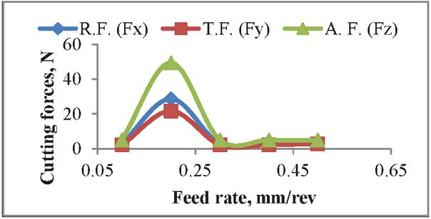
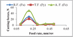
Figure 4 Cutting forces as a function of feed rate.
3.2 Impact on Cutting Forces by Feed Rate
Cutting speeds and depth of cut are maintained constant at 600 mm/min and 0.3 mm, respectively. The impact of feed variation on cutting forces is examined when feed is changed from 0.1 mm/rev to 0.5 mm/rev. Figure 4 shows the graph obtained for magnitude of all three cutting forces vs magnitude of feed rate. As feed increases, cutting forces also increases. A rise in feed causes the material removal rate to increase, which in turn causes a steady increase in the cutting force needed to achieve the material removal rate.

Figure 5 Cutting forces as a function of depth of cut.
3.3 Impact on Cutting Forces by Depth of Cut
The final adjustments were made to the cutting depth of 0.1 mm to 0.5 mm while keeping the feed rate and cutting speed at 600 mm/min and 0.3 mm/rev, respectively. Figure 5 shows the obtained graph for each of the three cutting forces’ magnitudes in relation to the depth of cut. The cutting forces’ magnitude increases slightly as the cut’s depth increases. Given that the axial thrust force rises as the cut depth increases, the axial cutting force grows more than the other.
4 Conclusions
In face milling Mg-Ca1.0 alloy, this study looked at how feed rate, cutting speed, and depth of cut affected the radial (Fx), tangential (Fy), and axial (Fz) cutting forces. With this experiment in mind, the authors came to the following conclusions:
• As cutting speed increased, the metal became softer and less resistant to the cutting motion, resulting in a decrease in the magnitude of all cutting forces.
• Cutting forces were increased as soon as the feed was initiated. Cutting force reductions of a lesser magnitude result from additional feed increases. An increase in feed causes the material removal rate to increase, and reaching the material removal rate requires a gradual increase in cutting force.
• The axial cutting force increased proportionately with the depth of cut due to the smooth shearing action against the workpiece and the tooth of the milling cutter.
• By enhancing the Mg-Ca1.0 alloy’s surface quality through various precision machining techniques, the alloy shows promise for use in biomedical and aerospace applications in the future.
Acknowledgement
The authors are grateful to the support of Dr. G. V. Garje, Joint Director, Technical Education, Regional Office Nashik & Principal, Government Polytechnic, Nashik, India. Also thankful to Dr. Babasaheb Ambedkar Technological University, LonereDist Raigad (MS) for providing the machining and measurement facility for the study.
References
[1] Jagtap K A and Pawade R S, Experimental Investigation on Surface Roughness of Face Turned Co-Cr-Mo Biocompatible Alloy Followed by Polishing, Journal of Materials Science & Surface Engineering, 5(4) (2017), 585–592.
[2] Jagtap K and Pawade R, Some investigations on surface roughness and cutting force in face turning of biocompatible Co-Cr-Mo alloy, Advanced Materials Proceeding, 3(4) (2018), 289–297.
[3] Jagtap K A, Pawade R S and Giradkar K V, Investigations on Surface Integrity and Electrochemical Behavior of Machined Co-Cr-Mo Bio-implant Alloy, International Journal of Advanced Design and Manufacturing Technology, 9(4) (2016), 51–58.
[4] Jagtap K A and Pawade R S, Some studies on chip formation mechanism in CNC turning of biocompatible Co-Cr-Mo alloy, Procedia Manufacturing, 20 (2018), 283–289.
[5] Jagtap K A, Investigation on Machined Surface Integrity in CNC Turning of Biocompatible Co-Cr-Mo Alloy, PhD Thesis, Dr. BATU, Lonere, India (2018).
[6] Trimble D, Agarwal A, MCdonnell D, Barron S, Ahearne E and O’Donnell G E, Finite Element Simulation of Orthogonal Machining of Biomedical Grade Co-Cr-Mo Alloy, CIRP Journal of Manufacturing Science and Technology, 28 (2020), 8–14.
[7] Sankaya M, Sirin S, Yildirim C V, Kivak T and Gupta M K, Performance evaluation of whisker-reinforced ceramic tools under nano-sized solid lubricants assisted MQL turning of Co-based Haynes 25 superalloy, Ceramics International, 47(11) (2021), 15542–15560.
[8] Ketan A. Jagtap and Raju S. Pawade, Monitoring of Surface Topography in CNC Turning of CoCrMo Biomaterial by using Acoustic Emission Signals, Surface Review & Letters, Vol. 29 No. 08 (2022), 2250108, 1–12.
[9] Tönsoff H. K. and Winkler J, The Influence of Tool Cutting in Machining of Magnesium, Surface and coating Technology, 94–95, (1997), pp. 610–616.
[10] Fang Chai, Datong Zhang and Yuanyuan Li, Microstructures and tensile properties of submerged friction stir processed AZ91 magnesium alloy, Journal of Magnesium and Alloys Volume 3, Issue 3, (2015), pp. 203–209.
[11] Péter Ozsváth, Attila Szmejkál, János Takács, Dry milling of magnesium based hybrid materials, Polytech. Transp. Eng., Vol. 36, No. 1–2, (2008), pp. 73–78.
[12] Salahshoor M., Guo Y. B., Cutting Mechanics of High Speed Dry Machining of Magnesium-Calcium Biomedical Alloy Using Internal State Variable Plasticity Model, International Journal of Machine Tools and Manufacture, 51(7), (2011), pp. 579–590.
[13] Gu, X., Zheng Y., Cheng Y., Zhong S., Xi T., In vitro corrosion and biocompatibility of binary magnesium alloys. Biomaterials, 30, (2009) pp. 484–498.
[14] Zhou N., Zhang Z., Jin L., Dong J., Chen B., Ding W., Ductility improvement by twinning and twin–slip interaction in a Mg-Y alloy. Mater. Des., 56, (2014) pp. 966–974.
[15] Zheng K.Y., Dong J., Zeng X.Q., Ding W.J., Effect of thermo-mechanical treatment on the microstructure and mechanical properties of Mg–6Gd–2Nd–0.5Zr alloy. Mater. Sci. Eng. A, (2007) pp. 454–455.
[16] Xiao B.L., Yang Q., Yang J., Wang W.G., Xie G.M., Ma Z.Y., Enhanced mechanical properties of Mg–Gd–Y–Zr casting via friction stir processing. J. Alloy. Compd., 509, (2011) pp. 2879–2884.
[17] Li J., Zhang D. T., Chai F., Zhang W., Microstructures and mechanical properties of WE43 magnesium alloy prepared by friction stir processing. Rare Met., (2014) pp. 1–6.
[18] Junzhan Hou, Wei Zhou and N. Zhao, Effect of Cutting Parameters on Ignition of AM50A Mg Alloy during Face Milling, Materials and Manufacturing Processes 25(10), (2010) pp. 1048-1051.
[19] Kim J. and Lee K., Surface Roughness Evaluation in Dry-Cutting of Magnesium Alloy by Air Pressure Coolant, Engineering, Vol. 2, No. 10, (2010) pp. 788–792.
[20] Xuan Guo, Guodong Liu, Shunheng Sang, Qichao Lin and Yang Qiao, Characteristics and Surface Serviceability for Cryogenic Milling Mg-1.6Ca-2.0Zn Medical Magnesium Alloy, Journal of Functional Biomaterials, Vol. 13(4), (2022), pp. 1–16.
[21] Ketan A. Jagtap and Raju S. Pawade, Monitoring of Surface Topography in CNC Turning of CoCrMo Biomaterial by using Acoustic Emission Signals, Surface Review & Letters, Vol. 29, No. 08, (2022), 1–12.
Biographies

Ketan Jagtap has completed Ph.D. in Mechanical Engineering from Dr. Babasaheb Ambedkar Technological University, Lonere, Dist. Raigad, Maharashtra, India in Aug. 2018. He is currently working as a Lecturer in Mechanical Engineering at Government Polytechnic, Nashik, Maharashtra. He has published about 50 research papers in referred international journals, international conferences and national conferences. He’s also recipient of International and National Awards.

Suresh Sanap has completed ME in Manufacturing and Automation from Savitribai Phule Pune University, Pune in 2014. He has published papers in journals and conferences. He is currently working as a Head of Department of Mechanical Engineering at Government Polytechnic, Nashik, Maharashtra.
Journal of Graphic Era University, Vol. 12_1, 77–88.
doi: 10.13052/jgeu0975-1416.1215
© 2024 River Publishers