Analysis of Available Yawing Moment of an Autonomous Underwater Vehicle Model in Simulation Frame
Pritam Ghosh*, Anwesha Das and Pranibesh Mandal
Department of Mechanical Engineering, Jadavpur University, 132, Raja Subodh Chandra Mallick Rd, Jadavpur, Kolkata, West Bengal 700032, India
E-mail: pghosh_me@yahoo.com; anweshadas1808@gmail.com; pranibesh.mandal@jadavpuruniversity.in
*Corresponding Author
Received 11 March 2023; Accepted 13 June 2023; Publication 31 July 2023
Abstract
Research endeavors on the design and control techniques of Autonomous Underwater Vehicles (AUVs) have been going on for a long time. In the present study, the yaw motion of a small submerged underwater vehicle is investigated and visualized as a direct result of changes in the rudder tilt angle and forward velocity. The numerical analysis is performed in ANSYS-Fluent software. The turbulent flow field has been modeled using Shear Stress Transport (SST) k- model. A grid independence test has been conducted to ensure the validity of the findings. The forces on the rudder and the available yaw moment have been obtained for different combinations of the AUV’s rudder tilt angle and forward velocity. The trend has intuitively been consistent and agreed with the basic concept of hydrodynamics.
Keywords: Underwater vehicle, yawing moment, rudder tilt angle, shear stress transport (SST) k- model, pressure distribution around on AUV rudder, CFD.
1 Introduction
Autonomous underwater vehicles (AUVs) have a wide range of applications because of their small size, low weight, strong ability to operate autonomously, and ability to replace humans in dangerous operations. AUV motion control systems have drawn a lot of attention from researchers in the fields of military operations and data acquisition for commercial purposes as well as underwater exploration. These AUVs are also being used in the exploration of a priori unknown environments [1], coastal management [2], sub-sea mapping, and undersea structure surveys [3] by industries. More study is being devoted to building and optimizing such vehicles due to their potential utility in numerous fields. The design and experimental testing of AUVs is complicated procedures. However, with the advent of powerful computational tools, the process can be simulated with reasonable accuracy. In 1998, Yuh et al. [4] contributed to the research in this domain in its early stages. They put forth the design of a Semi-Autonomous Underwater Vehicle for Intervention Missions (SAUVIM). Since then, a lot of literature has been published on AUVs and their motion control strategies to overcome the challenges introduced by system uncertainties and external disturbances [5, 6], often inspired by marine animals [7]. Manoeuvring underwater has often been attained using Variable Ballast Systems (VBS), which command motion by changing the mass of the vessel [8–10]. Besides the VBS, another innovative way to manoeuvre and stabilize an underwater vehicle is the use of a mechanical pectoral fin [11]. In 2016, Ahmed et al. [12] studied and evaluated various available methods for controlling depth and a similar analysis for low-speed and long-range AUVs have been performed by Bi et al. [13] in 2020. Ghosh and Mandal [14] have performed an analysis on the depth control of an AUV utilizing four ballast tanks to govern the vessel motion.
Despite depth control, yaw control of AUV in an underwater environment has been an area prompting ample research as the control technique greatly impacts the manoeuvrability of the vessel. Various earlier research papers have discussed the methodology for yaw motion control. Shang et al. [15] developed a prototype of a bio-mimetic underwater vehicle with two symmetrical bilateral long-fins for controlling yaw motion. They also suggested a fuzzy logic PID-based control strategy to control the vehicle’s yaw angle based on the architecture of the control system and driving system. In 2015, Patel et al. [16] have worked on the control strategy for the study of a third-order model designed for the yaw plane dynamics of an autonomous underwater vehicle. However, the first-principles-based mathematical models created for AUVs have been based on several assumptions and use estimated coefficients to describe the dynamics and hazy oceanic conditions, so they could not be a genuine depiction of the system in question. Yaw controller in the sliding mode for underwater autonomous vehicles has been studied by Valeriano et al. [17]. They have discussed the approach for the slider in their study as well as the outcomes it provides for the autonomous underwater vehicle, HRC-AUV, developed by Robotics and Automation Group Perception (GARP). The three-DOF nonlinear dynamics model defining HRC-AUV in the horizontal plane has been used to develop the direction control in sliding mode. Variable ballast systems have been improved upon [18, 19] and novel rudder designs have also been introduced to allow hovering motion as well as to study the change in yaw dynamics. Zhang et al. [20] have addressed the impact of using a quadruple X-rudder in an AUV vessel. In a more recent study, a review of the trajectory tracking and control strategies has been studied by Daoliang Li and Ling Du [21]. Three important factors have been taken into account in the control field: the importance of AUV trajectory tracking control, control techniques, and control effectiveness. Another study has been undertaken by Qi and Su [22] in recent times on an integrated roll and yaw control method for an AUV diving near the surface while being affected by random waves. They have employed the sliding mode variable structure control theory to design the roll and yaw integrated controller of the AUV in their study, based on the mathematical model of an existing AUV. To assess the effectiveness of the controller, a statistical analysis of the standard deviation of roll and yaw angle has been performed. In 2022, Liu et al. [23] have investigated the yaw motion control system of autonomous underwater vehicles based on a fractional-order proportional-integral-derivative (FOPID) controller to remove the significant uncertainties of the dynamic and hydrodynamic characteristics of the control systems as well as the time delay of the signal transmission channel. Similar work has been undertaken in the current year by Abdulkader [24] on the AUV dynamical system utilizing a Fractional Order Proportional Integral (FOPI) controller, which has enhanced the regulation of steering angle for AUVs. To monitor the yaw angle of the structure, the FOPI controller has been compared to the traditional Integer Order Proportional Integer (IOPI) controller using the MATLAB-Simulink programming platform for validation.
In the present study, an innovative small AUV model proposed by Ghosh and Mandal [14] has been considered for yaw motion analysis. The primary objective of this study is to analyze the impact of various orientations of the submarine rudder on the yaw dynamics of the vessel. The available yawing moment is dependent on the pressure variation on the rudder, it is necessary to find out such pressure variation for various rudder angle settings. Again, the pressure variation on the rudder is very much dependent on the forward velocity of the submarine underwater. So, the yaw motion of the submarine model is dependent on the forward motion as well. Very few present literatures have addressed the yaw control of an AUV based on forward movement and subsequent pressure variation on the rudder. Here is the novelty of the present work. The forces acting on the rudder due to the pressure variation and consequently, the available yawing moment have been obtained as functions of varying tilt angle of the rudder as well as the forward velocity of the AUV. The total analysis has been carried out using CFD simulation in the ANSYS-FLUENT software platform and the trend is presented illustratively.
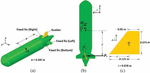
2 System Description and Modeling
A small-scale Autonomous Underwater Vehicle model, as proposed by Ghosh and Mandal [14], has been considered for the study. The hull longitudinally measures 1m and the maximum breadth spans 0.2 m with the height being 0.16 m. The geometry has been developed in SolidWorks as shown in Figure 1(a). There are control accessories and ballast tanks inside. However, only the effects on motion associated with the rudder have been considered for the present study. The propeller has been assumed to have no impact on motion due to its geometry. The rudder geometry has been an important parameter for the study. It is of trapezoidal shape, 0.125 m in length at the bottom and 0.05 m at the top, with a thickness of 0.0125 m. In between the four fin-like surfaces shown in Figure 1(a), only the vertical one at the top is movable and works as the rudder. The others are fixed fins only used for stability purposes. The difference in water pressure occurs on the two sides of the rudder if it is tilted sidewise while the submarine is having forward velocity. It is due to the fact that the rudder while tilted at a particular angle (), renders an angle of attack equal to the angle of tilt () with the free stream velocity of water particles. Water has been considered stagnant for the analysis thereby causing the free stream velocity of the water particles to be equal and opposite to the forward velocity of the AUV. Such an angle of attack causes a difference in the overall pressure distribution on the two sides of the rudder thereby causing Lift-like side force, to be acting on the same as shown in Figure 1(b). Here it has been considered that such side force on the rudder acts at the ‘Centre of Area’, G of the planform area of the rudder surface as shown in Figures 1(b) and 1(c). Such a side force, renders a yawing moment () about the CG of the AUV in the plane as shown in Figure 1(b). The moment arm is also shown in Figure 1(b) and denoted as ‘r’. The moment arm is determined by adding the distances from the CG to the tip of the base of the rudder and the distance of G from the tip of the base as shown in Figures 1(a) and 1(c). It may be noted that as the rudder is rotated about an axis passing through G, the angular position of the rudder does not change the value of ‘c’. Also, for the present analysis, the CG of the AUV is a fixed point and the tip of the rudder is always a fixed point rendering the distance ‘a’ to be constant also. That necessarily means the moment arm ‘r’ is to be constant for the entire analysis and it is measured to be 0.513 m. So, the available yawing moment, can be given by:
| (1) |
is the total side force on the rudder for any instance.

Figure 1 (a) 3D view of model AUV. (b) Top view of the model AUV. (c) Planform area of the rudder.
Computational Fluid Dynamics (CFD) provides an interface to simulate fluid flow problems, among many others, by utilizing mathematical models and predicting the system behaviour based on them [14, 25, 26]. It saves a lot of resources that are required for experimental evaluation. In this analysis, the forces on the rudder of the immersed submarine have been predicted at various rudder angles and different forward velocities using the Shear-Stress Transport (SST) k- model [27]. This model was established in 1994, and since then, has been widely used for various simulations [28]. The governing equations for incompressible fluid flow are given by:
| (2) | |
| (3) | |
| (4) | |
| (5) |
Where, is the velocity component along the x, y, z-axis; is the fluid viscosity; p is the pressure; is the working fluid density; g is the gravitational acceleration; is the body force; is the turbulent eddy viscosity; is the generation of specific turbulence dissipation rate; is the generation of turbulence kinetic energy due to mean velocity gradient; is the effective diffusivity of turbulent kinetic energy; is the effective diffusivity of turbulent dissipation rate; and are the defined source terms of turbulent dissipation rate and turbulent kinetic energy respectively; and are the effective diffusivity terms; is the cross-diffusion term.
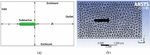
The lift force estimation generated by the submarine’s rudder has been analyzed using a 3-D model. The computational domain has been extended by a distance L in front of the leading edge of the underwater hull form and 2L behind the trailing edge as shown is shown in Figure 2(a). Here, L represents the length of the submarine model. The domain above and below the rudder and fixed fin are also extended by distance L for both cases as shown in Figure 2(a).
In this study water has been considered as working medium. For the numerical analysis of fluid flow around the submarine hull and rudder, pressure-based solver has been used and for pressure-velocity coupling, coupled system [29] has been employed. For the discretization of the momentum and turbulent models, a Least Squares Cell-Based technique [29] has been utilized in conjunction with a second-order upwind method. The boundary
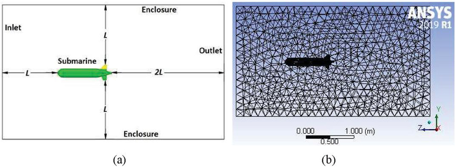
Figure 2 (a) Details of Computational domain (b) Unstructured mesh of the computational domain.
Table 1 Boundary conditions for numerical analysis
| Boundary | Boundary Condition |
| Inlet | Velocity inlet |
| Outlet | Pressure outlet |
| Surface | No-slip boundary |
| Outer surface of Enclosure | Zero wall shear |
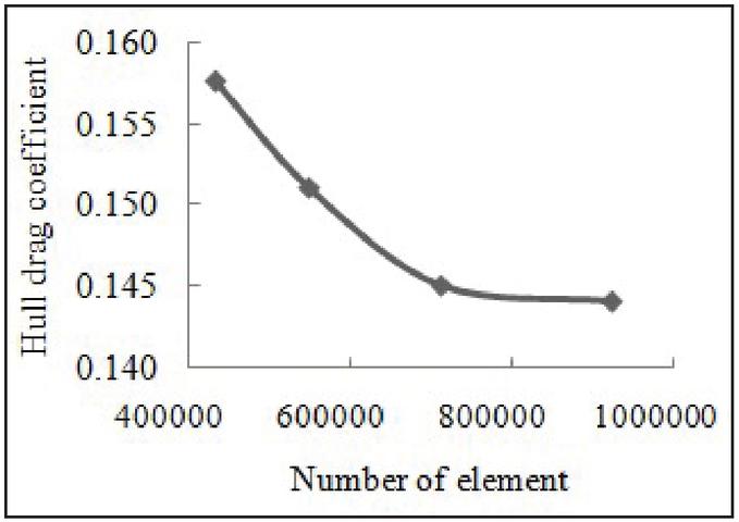
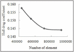
Figure 3 Grid independence test result.
conditions have been listed in Table 1. Grid independence testing has been an integral part of ensuring the validity of the solution technique while performing CFD operations in the ANSYS-Fluent package. A higher number of elements result in greater time for the computation to execute. It helps selecting a suitable mesh size and ensures accuracy. For grid independence study, solution domain has been tested with unstructured mesh having 0.43, 0.54, 0.71, and 0.92 million elements respectively, using Shear-Stress Transport (SST) k- model [27]. Is has been inferred from the grid independence study, the change in hull drag coefficient is least between 0.71 and 0.92 million elements as shown in Figure 3. Hence, 0.71 million elements have been chosen for the numerical analysis which corresponds to a hull drag coefficient 0.145. It has been found that grid independence test provides an optimum grid size to conduct the numerical simulation with reasonable accuracy.

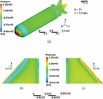
Figure 4 Pressure distribution for and m/s. (a) Pressure distribution on the whole surface of AUV. (b) Left surface of the rudder. (c) Right surface of the rudder.

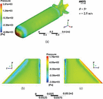
Figure 5 Pressure distribution for and m/s. (a) Pressure distribution on the whole surface of AUV. (b) Left surface of the rudder. (c) Right surface of the rudder.
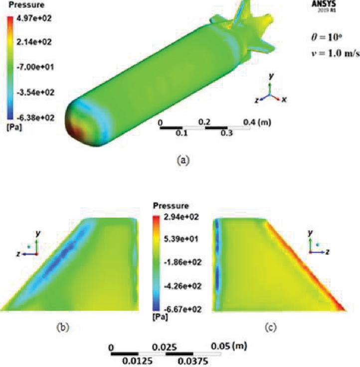
Figure 6 Pressure distribution for and m/s. (a) Pressure distribution on the whole surface of AUV. (b) Left surface of the rudder. (c) Right surface of the rudder.
3 Results and Discussion
The rudder has been tilted at various angles of attack () and also the forward velocity of the AUV has been varied in order to obtain their effects on the side force () on the rudder and thus on the available Yawing moment (). The analysis has been carried out in the ANSYS-FLUENT software platform in a 3D environment and the pressure variations have been shown in Figures 4 to 7 for several combinations of and . Figure 4(a) contains the pressure variation over the entire AUV model for and m/s while Figures 4(b) and 4(c) show the difference in pressure distribution over the two sides of the rudder for the same combination. It is evident that the pressure difference would lead to a side force and for this combination, the has been obtained as 0.538 N. It is to be mentioned that has been obtained from the pressure distribution using the inbuilt toolbox of the ANSYS-FLUENT software platform itself. Corresponding to the side force an available yawing moment can be calculated using Equation (1) and the value is coming to be 0.234 N-m. In the same way, Figures 5(a), 5(b) and 5(c) show respectively the pressure distributions on the entire AUV and those on the two sides of the rudder for and m/s. It is evident from the legend showing the pressure values, the overall pressure values have been increased with an increase in . The corresponding and have been obtained as 3.505 N and 1.526 N-m. So, it is evident that an increase in increases and thus as well. The pressure distributions on the overall AUV as well as on the two surfaces of the rudder have been shown in Figures 6 and 7 for an increased value of , equal to 10 while have been kept respectively at 1.0 m/s and 2.5 m/s. The corresponding values have been obtained respectively as 0.853 N and 5.419 N while the values have been calculated as 0.371 N-m and 2.36 N-m. It is evident from the figures that with the increase in the value of from 5 to 10, the side force and the corresponding yawing moment also increase.
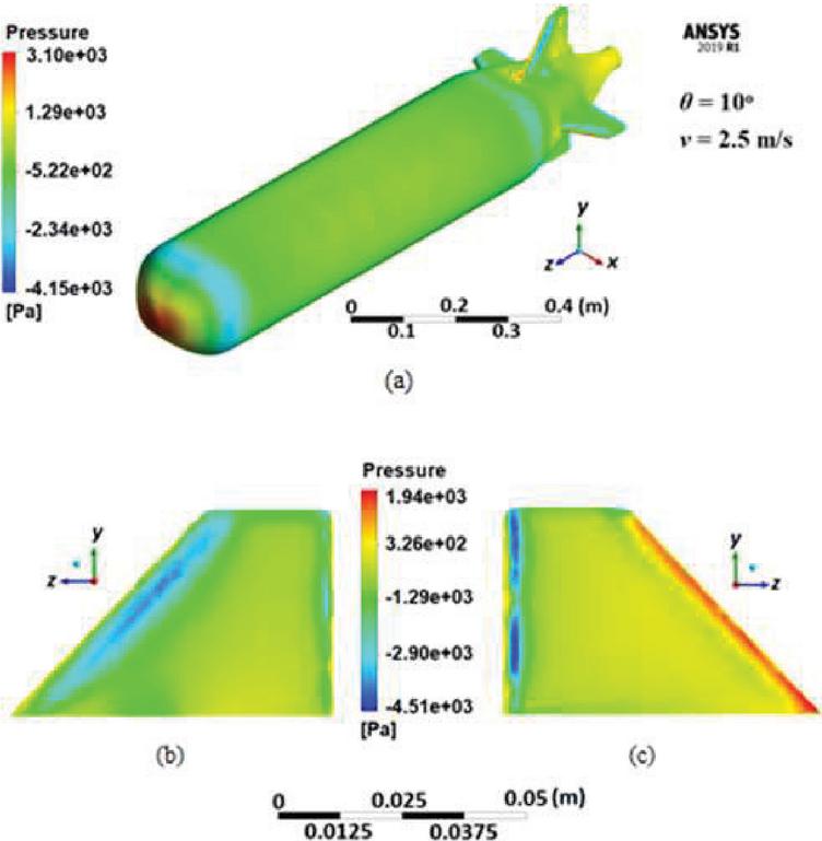
Figure 7 Pressure distribution for and m/s. (a) Pressure distribution on the whole surface of AUV. (b) Left surface of the rudder. (c) Right surface of the rudder.
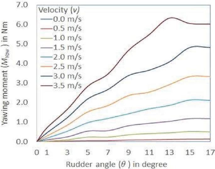
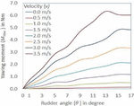
Figure 8 Variation of the available yawing moment with for different forward velocity.
Similar exercises have been carried out for a large number of and combinations and the available yawing moment, has been plotted with for different values in Figure 8. The curves show that is increased with the tilt angle up to a certain angle after which it tends to fall. This angle denotes the stalling angle of the rudder after which the Lift-like side force on the rudder tends to fall thereby causing to decrease. It is also evident that with the increase in the forward velocity () of the AUV, the Lift-like side force increases thereby resulting in an increase of . The stalling angle also tends to decrease for higher values. While for a forward velocity of 2.0 m/s, the stalling occurs at a tilt angle of around 15; for a higher forward velocity of 3.5 m/s, it comes down to an angle of around 13. So, it may be concluded that the operating range for the tilt angle of the rudder may be considered to be less than 11 or so to prevent it from getting stalled. For tilt angles ranging between 5 and 11 and for forward velocity values above 2.0 m/s, the available yawing moment values have been sufficiently above 1 N-m.
4 Conclusion
In the present study, the yaw motion of a small submerged underwater vehicle is investigated. A three-dimensional simulation analysis in the ANSYS-FLUENT software platform has been carried out to obtain the pressure distribution around an AUV model and especially on the two sides of a rudder placed at the backside and tilted at an angle ranging from 0 to 17 with the direction of forward velocities ranging from 0 to 3.5 m/s. Force on the rudder and the corresponding available yawing moment has been obtained for the AUV model from the pressure distribution for various combinations of the tilt angle of the rudder and forward velocity of the AUV. With the increase in tilt angle, and thus have been seen to have increased up to a certain angle of tilt (around 13 to 15) beyond which a fall in and have been noticed due to stalling. and have also increased with the forward velocity of the AUV model. A plot has been obtained for the variation of with the tilt angle for different forward velocity values as shown in Figure 8. It is clear from the Figure 8 that to minimize stalling the operating range for the rudder tilt angle should be less than or about 11 and to generate the yawing moment adequately over 1 N-m the rudder must be tilted at an angle between 5 & 11 along with a forward velocity of 2.0 m/s and above.
5 Future Scope of Work
The present study contains only the numerical analysis that involves assumptions. To eliminate these assumptions and to validate these numerical results, an experimental study is required. The experimental study of such a small AUV model for yaw motion control is the primary scope for future research. The effect of heave velocity on the yaw motion of an AUV is another scope of future study.
Acknowledgements
This research is supported by the Rashtriya Uchchattar Shiksha Abhiyan (RUSA) scheme of development for higher education in India.
References
[1] Gupta, S., Hare, J., and Zhou, S. (2012, October). Cooperative coverage using autonomous underwater vehicles in unknown environments. In 2012 Oceans (pp. 1–5). IEEE.
[2] Yu, X., Dickey, T., Bellingham, J., Manov, D., and Streitlien, K. (2002). The application of autonomous underwater vehicles for interdisciplinary measurements in Massachusetts and Cape Cod Bays. Continental Shelf Research, 22(15), 2225–2245.
[3] Maki, T., Ura, T., and Sakamaki, T. (2012). AUV navigation around jacket structures II: map based path-planning and guidance. Journal of marine science and technology, 17, 523–531.
[4] Yuh, J., Choi, S. K., Ikehara, C., Kim, G. H., McMurty, G., Ghasemi-Nejhad, M., … and Sugihara, K. (1998, April). Design of a semi-autonomous underwater vehicle for intervention missions (SAUVIM). In Proceedings of 1998 international symposium on underwater technology (pp. 63–68). IEEE.
[5] Feng, Y., Yu, X., and Han, F. (2013). On nonsingular terminal sliding-mode control of nonlinear systems. Automatica, 49(6), 1715–1722.
[6] Joe, H., Kim, M., and Yu, S. C. (2014). Second-order sliding-mode controller for autonomous underwater vehicle in the presence of unknown disturbances. Nonlinear Dynamics, 78, 183–196.
[7] Murphy, A. J., and Haroutunian, M. (2011). Using bio-inspiration to improve capabilities of underwater vehicles. In 17th International Symposium on Unmanned Untethered Submersible Technology (UUST). Newcastle University.
[8] Tangirala, S., and Dzielski, J. (2007). A variable buoyancy control system for a large AUV. IEEE Journal of Oceanic Engineering, 32(4), 762–771.
[9] Woods, S. A., Bauer, R. J., and Seto, M. L. (2012). Automated ballast tank control system for autonomous underwater vehicles. IEEE Journal of Oceanic Engineering, 37(4), 727–739.
[10] Font, R., and García-Peláez, J. (2013). On a submarine hovering system based on blowing and venting of ballast tanks. Ocean Engineering, 72, 441–447.
[11] Kato, N., and Liu, H. (2003). Optimization of motion of a mechanical pectoral fin. JSME International Journal Series C Mechanical Systems, Machine Elements and Manufacturing, 46(4), 1356–1362.
[12] Syed, F. A., Hazry, D., and Abadal, S. (2017). Study of depth control method for Unmanned Underwater Vehicle (UUV). Journal of Environmental Science and Technology, 10(2), 88–95.
[13] Bi, A., Zhao, F., Zhang, X., and Ge, T. (2020). Combined depth control strategy for low-speed and long-range autonomous underwater vehicles. Journal of Marine Science and Engineering, 8(3), 181.
[14] Ghosh, P., and Mandal, P. (2019). Numerical study of depth control of an innovative underwater vehicle having four ballast tanks. International Journal of Emerging Technologies and Innovative Research, 6(5), 123–126.
[15] Shang, L., Wang, S., and Tan, M. (2010, October). Fuzzy logic PID based control design for a biomimetic underwater vehicle with two undulating long-fins. In 2010 IEEE/RSJ International Conference on Intelligent Robots and Systems (pp. 922–927). IEEE.
[16] Patel, S. S., Kumar, K., Botre, B. A., and Akbar, S. A. (2015, December). Design of fuzzy logic based controller with pole placement for the control of yaw dynamics of an Autonomous underwater vehicle. In 2015 Annual IEEE India Conference (INDICON) (pp. 1–6). IEEE.
[17] Valeriano, Y., Fernández, A., Hernández, L., and Prieto, P. J. (2016). Yaw controller in sliding mode for underwater autonomous vehicle. IEEE Latin America Transactions, 14(3), 1213–1220.
[18] Vasilescu, I., Detweiler, C., Doniec, M., Gurdan, D., Sosnowski, S., Stumpf, J., and Rus, D. (2010). AMOUR V: A hovering energy efficient underwater robot capable of dynamic payloads. The International Journal of Robotics Research, 29(5), 547–570.
[19] Zhao, X., Liu, Y., Han, M., Wu, D., and Li, D. (2016). Improving the performance of an AUV hovering system by introducing low-cost flow rate control into water hydraulic variable ballast system. Ocean Engineering, 125, 155–169.
[20] Zhang, Y., Li, Y., Zhang, G., Zeng, J., and Wan, L. (2017). Design of X-rudder autonomous underwater vehicle’s quadruple-rudder allocation with Lévy flight character. International Journal of Advanced Robotic Systems, 14(6), 1729881417741738.
[21] Li, D. and Du, L. (2021). AUV Trajectory Tracking Models and Control Strategies: A Review. Journal of Marine Science and Engineering, 9(1020).
[22] Qi, Z. and Su, Y. (2021). Research on Integrated Roll and Yaw Control Strategy for AUV Diving Near Surface. 40th Chinese Control Conference (CCC) 2021, (pp. 2339–2343), Shanghai, China.
[23] Liu, L., Zhang, L., Pan, G., and Zhang, S. (2022). Robust yaw control of autonomous underwater vehicle based on fractional-order PID controller. Ocean Engineering, 257, 111493.
[24] Abdulkader, R. (2023). Controller Design based on Fractional Calculus for AUV Yaw Control. Engineering, Technology & Applied Science Research, 13(2), 10432–10438.
[25] Chruściel, T., Ciba, E., and Dopke, J. (2014). CFD and FEM model of an underwater vehicle propeller. Polish Maritime Research, 21(3), 40–45.
[26] Bose, G. K., Ghosh, P., and Pal, D. (2019). Analytical and Numerical Modelling of Liquid Penetration in a Closed Capillary. In Process Analysis, Design, and Intensification in Microfluidics and Chemical Engineering (pp. 114–135). IGI Global.
[27] Menter, F. R. (1994). Two-equation eddy-viscosity turbulence models for engineering applications. AIAA journal, 32(8), 1598–1605.
[28] de Sousa, J. V. N., de Macêdo, A. R. L., de Amorim Junior, W. F., and de Lima, A. G. B. (2014). Numerical analysis of turbulent fluid flow and drag coefficient for optimizing the AUV hull design. Open journal of fluid dynamics, 4(03), 263.
[29] ANSYS Workbench Products ReleaseNotes 10.0.
Biographies

Pritam Ghosh received the B.Tech. degree in Mechanical Engineering from WBUT, Kolkata, India, in 2014, and M. Tech. degree in Mechanics of Fluids from IIEST, Shibpur, Howrah, West Bengal, India, in 2016. Currently, he is pursuing Ph.D. degree in Mechanical Engineering at Jadavpur University, Kolkata, India. His areas of research are Capillary driven flow and Autonomous Underwater Vehicles design.

Anwesha Das is pursuing B.E. degree in Mechanical Engineering from Jadavpur University, Kolkata. Her areas of interest in research include Microfluidics, Multiphase flows, and Autonomous Underwater Vehicle control.

Pranibesh Mandal is working as an Assistant Professor in the Department of Mechanical Engineering since January 2014 at Jadavpur University, Kolkata, India. He is currently doing research in Applied Aerodynamics, Underwater Vehicle Design, Hydraulic Control, Experimental Fluid Mechanics and Heat Transfer as well as other related fields.
Journal of Graphic Era University, Vol. 11_2, 191–206.
doi: 10.13052/jgeu0975-1416.1125
© 2022 River Publishers