Design for Improvement of COP from Waste Heat Utilization Through Air Conditioning System
Saba Sabir1, Hitesh Pant2,*, Nikhi Kanojia1 and Kuldeep Rawat1
1Department of Mechanical Engineering, Shivalik College of Engineering, Dehradun, Uttarakhand, India
2Frontier Media SA, Comeniusstrabe, Dresden, Germany
E-mail: hitesh.pant87@gmail.com
*Corresponding Author
Received 13 March 2022; Accepted 01 April 2022; Publication 04 March 2023
Abstract
Energy is in higher demand than ever before since there are an increasing number of applications for it; nevertheless, the existing sources are unable to supply it in sufficient quantities. Alternate energy sources should be utilized, and as a consequence, energy conservation should be achieved through the utilization of waste heat from air conditioning systems. The major objective of this piece is to make use of waste heat generated by residential air conditioning systems while simultaneously increasing the coefficient of performance (COP). In order to achieve this goal, an experimental setup is utilized. In this configuration, an indirect kind of heat recovery equipment is used, and a heat exchanger that converts heat from a refrigerant to water is positioned between the compressor and the condenser of the host refrigeration system. The hot refrigerant gas generated by the compressor is sent via one side of the heat exchanger, while water is forced through the other side. The temperature of the water is raised as a result of the heated refrigerant gas. Because of this, the system’s COP might potentially increase by up to 16%.
Keywords: Waste heat recovery, COP, heat exchanger, cooling effect, de-superheat, air-conditioning system.
1 Introduction
Energy is one of the most essential requirements for the expansion of human existence. The primary sources of energy used in commercial enterprises are hydroelectric power plants, nuclear power plants, and fossil fuels (including oil, coal, and natural gas). Due to atmospherically more destructive discharges of radiation in the form of nuclear waste, these kinds of energy are created based on the requirements of the nation. The focus shifts from alternative energy sources to more conventional ones, with an increased emphasis on energy conservation and responsible use.
At this point in time, the most important things to focus on are energy efficiency and conservation. The quantity of electricity that is used annually is steadily becoming higher as a direct result of the expanding market for window air conditioners. As a direct consequence of this, a brand-new standard for the energy efficiency of window air conditioners will be implemented in the not-too-distant future. To satisfy this criterion, it is necessary, as a result, to develop systems that are efficient in their use of energy. Therefore, the primary focus for developing energy-efficient systems need to be on enhancing the performance of the systems in question. This experimental device’s goal is to create an air conditioner with several uses system that can simultaneously provide hot water (by reusing the heat that is recovered from the region that is being cooled) and an air conditioning effect (cooling the space). This project presents an experimental setup that warms water for household and business use utilizing the excess heat produced by window air conditioners. The water may be used for both domestic and professional purposes. According to the findings of study, for every degree Celsius that the condenser’s temperature rises, an air conditioner’s coefficient of performance (C.O.P.) decreases by 2 to 4%. As a result, an air conditioner’s coefficient of performance (C.O.P.) might decrease by as much as forty percent when the temperature is high. As a result, the coefficient of performance of the air conditioner will directly correlate to the quantity of power that will be consumed.
1.1 What is Waste Heat?
Even if heat is “exhausted” into the environment as the result of the combustion of fuel, a chemical reaction, or the operation of any other type of mechanical system, it is possible that it might still be used for another purpose that is both useful and efficient. It is more important to consider the quality of the waste heat than its amount. The amount of heat that can be recovered is determined both by the quality of the waste heat gases (temperature) and the economics that are linked with them. The production of considerable quantities of hot flue gases is accomplished by furnaces, mechanical systems, and boilers. Because of this re-covery, we will be able to conserve a significant quantity of fundamental fuels. Using waste heat recovery technologies, it is possible for us to reclaim part of the lost energy.
1.2 Waste Heat Recovery System
Recovery of the superheated heat requires window air conditioning systems make use of a desuperheater, which is a sort of heat recovery technology (also known as waste heat). In its most basic form, a desuperheater is a waste heat recovery system that also includes a condenser. Although desuperheaters can be utilized either directly or indirectly, the indirect method is the one that has been chosen to be used in the heat recovery system for this project.
1.3 Heat Exchangers
Heat exchangers are widely used in large-scale industrial activities that need for either heating or cooling the surrounding environment. The heat that is lost or squandered throughout the course of a number of different industrial processes may be recovered via the utilization of heat exchangers and then put to use in the process of heating up another stream. It is possible for businesses to save a large amount of money by making use of heat exchangers to feed heat to other streams rather than turning to an external source of heat that is both costly and harmful to the environment.
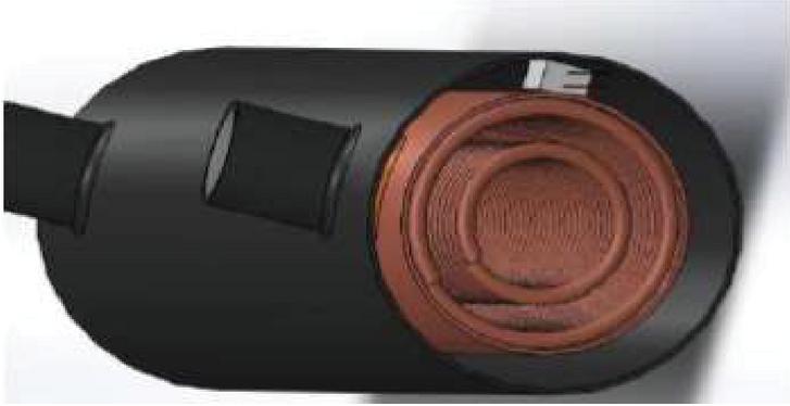
Figure 1 Heat exchanger coil.
Heat exchangers are used in many industries, including:
• Waste water treatment
• Refrigeration
• Wine and beer making
• Petroleum refining
• Nuclear power
2 Design of Heat Recovery System
Making a system for recovering waste heat through utilizing the window air conditioner’s capacity for desuperheating the air. The rated condition of the window air conditioner is used to calculate the available waste heat, and the design of the heat exchanger is used to determine how much heat can be recovered from it.
2.1 Design of Heat Exchanger Unit
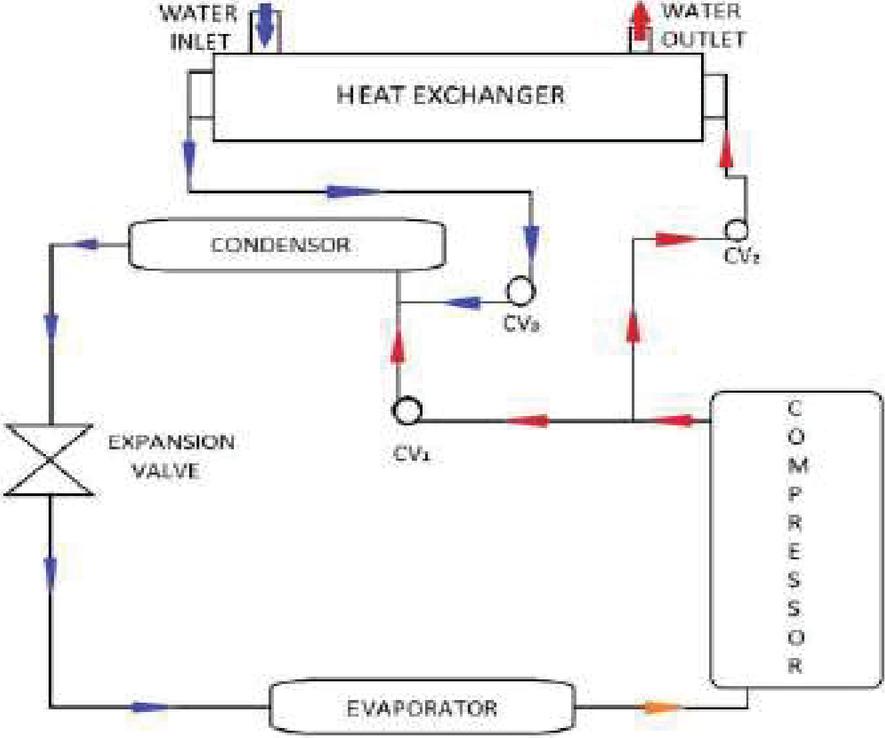
Figure 2 Schematic diagram of waste heat recovery form air conditioner.
2.2 Technical Specification
Air conditioner Model number: AH5522E Equipment rating: Single phase, 220V, 50Hz, 8.5A Power rating: 1.870kW Refrigerant: R-22 (CHClF2) Normal capacity: 1.5 TR Compressor: Hermitically Shield Displacement Type Condenser: Force convection air cooled Evaporator: Force convection air cooled Pressure gauge: One for suction pressure & one for discharge pressure Temperature Indicator: Digital Thermometer Controlvalve:
1. In between compressor dischargesand condenser (CV1).
2. In between heat exchanger suction and compressor (CV2).
3. In between heat exchanger outlet and condenser inlet (CV3).
2.3 Methodology
1. Calculation of energy supplied for refrigeration effect
2. Design of heat exchanger unit
3. Measurement of heat collected in heat exchanger unit.
4. Calculation of COP for normal air conditioning system
5. Calculation of COP for air conditioning system with exhaust heat collection using heat exchanger.
6. Comparison of COP in both above cases.
7. Conclusion
3 Design Process
3.1 Calculation of Energy Supplied for Refrigeration Effect
Input power of Air conditioner unit 1.870 kW 1870 W 1870 J/sec.
3.2 Design of Heat Exchanger Unit
When the refrigerant is desuperheated, how much heat is removed?
At 35C Ambient Temperature
Compressor inlet/suction pressure;
Pi 60 psi
Pi 60 6895 {1 psi 6895 Pa}
Pi 4.137 bar
Discharge pressure;
Po 250 psi
Po 250 6895
Po 17.2375 bar
Condenser Temperature 45C 318 K
Condenser pressure 17.2375 bar
Compressor inlet 4.137 bar
Compressor Outlet 17.2375 bar
Cooling capacity 1.5 TR 1.5 3.5 5.250 kW
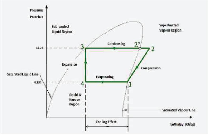
Figure 3 Pressure enthalpy plot.
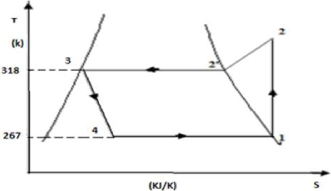
Figure 4 T-S diagram for refrigeration cycle.
By Interpolation
T1 6 (4.13 4.09172)/(4.3797 4.09172) 2 273
T1 267.266 K
T3 T2 45C 318 K
From R-22 Table: h 3 hf3 105.58 kJ/kg. h2
h 1 hg1 (250.30 249.46)/2 249.88 kJ/kg
Refrigerating Effect h1 h3
(249.88 105.58) kJ/kg
R.E. 144.3 kJ/kg
Mass Flow Rate of Refrigerant
mr (5.25 kJ/sec)/(144.3 kJ/kg)
mr 0.0364 kg/sec
For Superheated temperature (T2)
i.e S1 S2
At P 4.13 bar; S1 Sg1 0.94105 kJ/kg
At P 17.34 bar; S2 0.8755 kJ/kg
S2 S2 Cp ln (T2/T2)
S2 0.94105 0.8755 1.0256 ln (T2/318)
T2 338.9882 K {(Cp) R-22 1.0256 KJ/Kg}
T2 65.988C 660C
Enthalpy of Superheated Refrigerant
h 2 h2 Cp (T2 T2)
h 2 263.67 kJ/kg at P2 17.34 bar
h 2 263.67 1.0256 (338.9882 3.18)
h 2 285.2076 kJ/kg
Heat Available for Desuperheater (Qsup.)
Qsup. mr (h2 – h2) 0.0364 (285.2076 263.67)
Qsup. 0.78397 kW 783.9686 W
Heat Exchanger Unit
Given Data:
Material selected copper
Thermal conductivity (k) 380 W/mk
Inner diameter of tube (Di) 6.4 mm
Outer diameter of tube (Do) 8.0 mm
Fouling factor for refrigerant (Fr) 0.000095
Fouling factor for water (Fw) 0.000095
Thickness of tube (t) 1.6/2 0.8 mm
Heat transfer co-efficient for refrigerant side; hi 898 W/mK
Heat transfer co-efficient for water side; hw 151.85 W/mK
Overall heat transfer co-efficient
1/U 1/hi 1/ hw dx/Kcu Fr Fw
1/898 1/151.58 0.8/380 0.000095 0.000095
U 99.94 W/mK
To Find Out Area of Heat Exchanger
Find the water’s outflow temperature now.
Initial temperature; Tw1 25C
Qsup. mw *Cpw *T
783.9686 (0.5/60) 4.2 103 (Tw2 25)
Tw2 47.3991C 47C
By Using Log Mean Temperature Difference (LMTD) method (Tm)
T1 (66 47) C 19C
T2 (45 25) C 20C
LMTD (T1 T2)/ln(T1/T2) (19 20)/ln(19/20)
LMTD 19.496C
Now, Area of Heat Exchanger
Qsup. U* A*LMTD(Tm)
783.9686 99.94*A*19.496
A 0.4024 m
To Find Length of Pipe
A *Do *L
0.4024 * 8* L * 10
L 16.0095 m (i.e Figure 1)
Heat Absorbed by Water in Heat Exchanger
Table 1 Temperature of water
| Flow Rate of Water LPM | Inlet Temp. of Water OC | Outlet Temp. of Water OC |
| 0.5 | 25.3 | 52 |
Heat absorbs by water in heat exchanger
Qw mw* cpw*T
0.5*4.2*103*(52 28.2)/60
Qw 829.5 W
4 Calculation of COP for Normal Air Conditioning System
(COP) th Refrigeration Capacity/power input Cooling effect/power input 5.25/1.870 (COP) th 2.8075
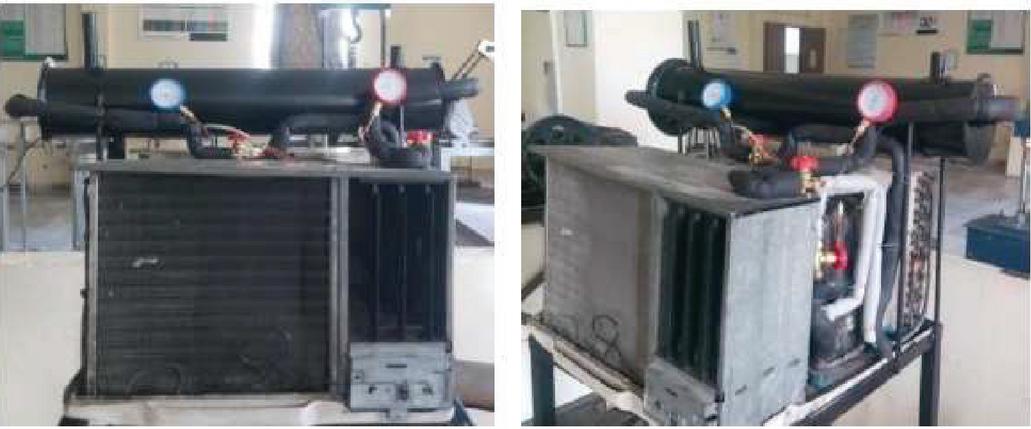
Figure 5 Experimental set up.
5 Calculation of COP for Air Conditioning System with Exhaust Heat Collection Using Heat Exchanger
COP (Refrigeration Capacity heat absorb by water in heat exchanger)/input power to air conditioning unit (5.25 103 W 829.5 W)/ (1.870 103 W) (COP)th 3.2511.
Percentage Increase in COP Theoretically
(3.2511 2.8075) 100/2.8075
15.7945% 16%
Validation and Discussion of Results
Within the scope of our investigation, we developed a heat exchanger that makes effective use of the waste heat produced by air conditioners (heating of water). The utilization of a desuperheater is an effective means by which temperature fluctuations brought on by superheating may be brought under control.
The air conditioner’s COP (Coefficient of Performance) can be raised by using a heat exchanger. To do this, waste heat from the air conditioner is used to warm the water. We are able to increase the COP of AC by up to 16% thanks to the desuperheater.
Conclusions and Recommendations for Future Work
On the basis of the models and research on the waste heat recovery from air conditioners that were described in the chapters before this one, one may reach the following conclusions:
The addition of the heat exchanger and the air conditioner increases the system’s C.O.P. (coefficient of performance) by 16%.
• There is less thermal pollution.
• Waste heat is put to use for something beneficial (heating of water).
• By controlling the rate at which water passes through the heat exchanger, it is possible to bring the temperature of the refrigerant down to the level that is needed.
Future Aspect of Our Project
• Given the limited availability of traditional energy sources, we have no choice but to make efficient use of the energy at our disposal. As a result, we will be able to make more productive use of the waste heat produced by this system, while simultaneously increasing the effectiveness of the air conditioner.
• It can be used in nursing homes, industrial settings, hotels, hotel mess areas, and other places that need hot water.
• The production of two hundred to five hundred watts of power through the use of a thermocouple that has been constructed appropriately and is built from a material that has a lower excitation temperature.
References
[1] Srinivasan, V., Christensen, R., “full-scale, testing, and analysis of an innovative natural-convection-driven heat-recovery heat exchanger for space-conditioning applications,” Heat Transfer Engineering, vol. 15, pp. 44–54, 1994.
[2] Prabhanjan, D. G. T. J. Rennie and Vijaya Raghavan, G. S. (2004, 4). Natural convection heat transfer from helical coiled tubes. International Journal of Thermal Sciences 43(4), pp. 359–365, 2004.
[3] Jayakumar, J. S. Mahajani, S. M. Mandal, J. C. Vijayan, P. K. and Bhoi, R., Experimental Prediction of Heat Transfer Correlations in Heat Exchangers by Tomasz, 2008.
[4] R.B. Lokapure, J.D. Joshi, e-ISSN: 2278-067X, p-ISSN: 2278-800X, www.ijerd.com Volume 5, Issue 3 (December 2012).
[5] Panwar, K, Murthy, D, S, “Analysis of thermal characteristics of the ball packed thermal regenerator”, Procedia Engineering, 127, 1118–1125.
[6] Panwar, K, Murthy, D, S, “Design and evaluation of pebble bed regenerator with small particles”, Materials Today, Proceeding, 3(10), 3784–3791.
[7] Bisht, N, Gope, P, C, Panwar, K, “Influence of crack offset distance on the interaction of multiple cracks on the same side in a rectangular plate”, Frattura ed Integrità Strutturale” 9(32), 1–12.
[8] Panwar, K, Kesarwani, A, “Unsteady CFD Analysis of Regenerator”, International Journal of Scientific & Engineering Research, 7(12), 277–280.
[9] Singh, I., Bajpai, P. K., and Panwar, K. “Advances in Materials Engineering and Manufacturing Processes.
Biography

Hitesh Pant has received his bachelor’s degree in Computer Science from Kumaon University Dwarahat in 2009. He has an expertise in designing developing and architecting complex data & AI driven software application in various domains. Currently he is working as a Software Engineering Manager at Frontiers living in Dresden, Germany, As an Engineering manager he is leading & building a team consisting of Senior engineers, Data engineers & Scientist for creating AI based data intensive distributed systems for simplifying peer review process of scientific articles & journals.
Journal of Graphic Era University, Vol. 11_1, 57–68.
doi: 10.13052/jgeu0975-1416.1115
© 2023 River Publishers