Transient CFD Analysis of Thermal Regenerator
Nikhil Kanojia
Department of Mechanical Engineering, Shivalik College of Engineering, Dehradun, Uttrakhand, India
E-mail: menikhilkanojia@gmail.com
Received 17 May 2022; Accepted 22 July 2022; Publication 04 March 2023
Abstract
The goal of the work is to analyze the impact of various factors on the fixed bed regenerator’s thermal characteristics while also examining the regenerator’s thermal characteristics. The thermal parameters of the regenerator are affected by a number of factors, including Heat storage capacity, switching time, residence time, bed height/length, regenerator diameter, particle diameter, and gas flow direction. The current study examines each of these variables quantitatively. Understanding the thermal regenerator’s temperature and fluid flow variations CFD analysis is conducted. For the analysis, Ansys Fluent is a for-profit program.
Keywords: Ansys Fluent, CFD, unstable, regenerator, thermal characteristic.
1 Introduction
A thermal One sort of heat exchanger is a heat regenerator. that con-tains a bed of solids (metals or ceramics) of various shapes that have a high volumetric heat capacity, or the ability to absorb and store a lot of heat. The two cycles of the thermal regenerator—the heating cycle and the cooling cycle—make up its whole operation. Hot gases from any manufacturing business, including the glass production industry, are pro-duced to travel through the regenerator during the heating cycle. The solids get heat from the flue gases, while flue gas-es from the regenerator exist at a lower temperature. Follow-ing the completion of the heating cycle, the regenerator bed is entered with cold air to begin the cooling cycle. Now that the heat has been transferred to the solids, cold air is heated. Recuperators, on the other hand, have a wall that separates the fluids that need to allow for the movement of heat from one to a different one. The fluids in recuperators serve as the medium for the transmission of heat between one another. are not mixed. As opposed to recuperators, which transmit heat through the wall, storage type heat exchangers (thermal regenerators) store and reject heat by solids. A parallel heat regenerator is seen in Figure 1 and is necessary for the flow of warm air that is constant [1].
2 Review of Literature
In the case of a fully developed flow, the pressure drop inside the regenerator can be found by using the equation [2] developed by Ergun. The constraint imposed by this equation is that it can only be used for large D/dp ratios (more than 15), in which case uniformity in the void % is essential.
3 Review of Literature
In the case of a fully developed flow, the pressure drop inside the regenerator can be found by using the equation [2] developed by Ergun. The constraint imposed by this equation is that it can only be used for large D/dp ratios (more than 15), in which case uniformity in the void % is essential.
The Ergun’s equation is: (1)

Figure 1 Fixed bed parallel heat regenerator [1].
Both of the coefficients, 150 and 1.75, in Ergun’s equation, which are represented by the number 1, are the subject of heated discussion and are universally opposed. Additionally, Hicks [3] presented a formula that estimates the pressure drop in a fixed-bed reactor by utilizing spherical particles. The coefficients in this formula, on the other hand, are not constant; rather, they change depending on the Reynolds number. In a subsequent investigation, According to the findings of Handly and Heggs [4], Ergun’s equation is unable to effectively forecast the pressure that is present in an unevenly packed bed regenera-tor. [Citation needed]. One of the findings of the investigation was that this was the case. Another equation to take into ac-count The decrease in pressure that takes place within a regenerator when it is operating. that has a fixed bed may be ex-pressed as: according to Mac-Donald [5].
All of the pressure equations discussed above apply to fixed bed regenerators with D/dp higher than 15. The flow complexi-ty is quite low in these situations because regenera-tors with D/d 15 are regarded to have homogeneity in void percentage in the bed. According to Einsfeld and Schnitzlein’s comprehensive assessment of wall effects in regenerators [6], Reichelt’s [7] correlation for pressure drop is the most promising one.
Only a highly An sophisticated tool for flow analysis such as Ansys Fluent can offer a comprehensive view of the flow struc-ture in regions that are physically near to the particles that make up these beds.
The current thesis aims to examine the complexity of the flow within the regenerator under a variety of different operating conditions, as well as to compute as the pressure decreased, temperature an alternative to the permanent bed using CFD simulations regenerators.
3.1 CFD Analysis
Heat transfer and fluid mechanics complicated issues are solved using computational fluid dynamics (CFD). CFD has been shown to be highly practical, helpful, and effective in situations when the geometries are too complicated to anticipate the flow and temperature distribution. Making the proper stratification decision requires a lot of work in experimental work, however CFD for regenerators can make the process much simpler [8].
Modern computer software called Ansys Fluent is utilized to mimic both the heat transfer and the movement of fluids. pro-cesses in challenging engineering scenarios.
Ansys-Design Modular was used to create the computational model forthe current investigation, and Ansys Fluent’s ICEM was used for meshing. To accurately reflect the effect of stratification within the regenerator, 5499 hexahedral cells with 6160 nodes were created. In Figure 2, an ICEM view of several meshes is displayed [10–14].
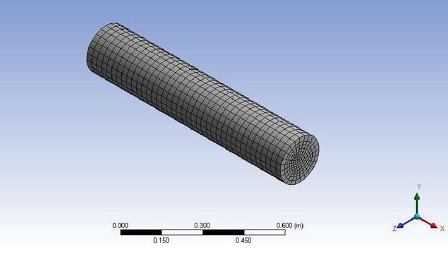
Figure 2 ICEM view of surface meshing.
3.1.1 Governing equations
The following are the governing equations that may be used to control the physical phenomena of flow through porous media. Murthy and Panwar [9]:
Continuty Equation:
| (1) |
Momentum Equation:
| (2) | |
The following equations are used to compute the viscous loss coefficient and the inertial loss coefficient of the porous zone:
| (3) |
where,
dp is the diameter of solid particle (alumina)
is the porosity of the regenerator bed
is the permeability
Viscous loss coefficient in each component direction 1/
| (4) |
where,
d is the diameter of solid particle (alumina)
is the porosity of the regenerator bed
C is the inertial loss coefficient
4 Results & Discussion
Ansys Fluent was used to represent the regenerator for transient CFD simulation. The simulation begins by forcing flue gases with a temperature of 473 Kelvin are introduced into the bed of the regenerator for a period of one minute every cycle. After the heating cycle has been completed, finished, the cooling cycle begins, lasting 60 seconds, air at 300 K entering the re-generator from the other side of the ambient flow.
Until the temperature flow reaches a stable level, flue gases during the heating cycle, and breathable air during the cool-ing cycle alternately flow. The length of the regenerator bed’s temperature curves during heating and cooling cycles are shown in Figures 3 and 4 at times of 1 and 2 minutes, respectively.

Figure 3 Temperature variation along regenerator length at plane y 0 for heating cycle at t 1 min.
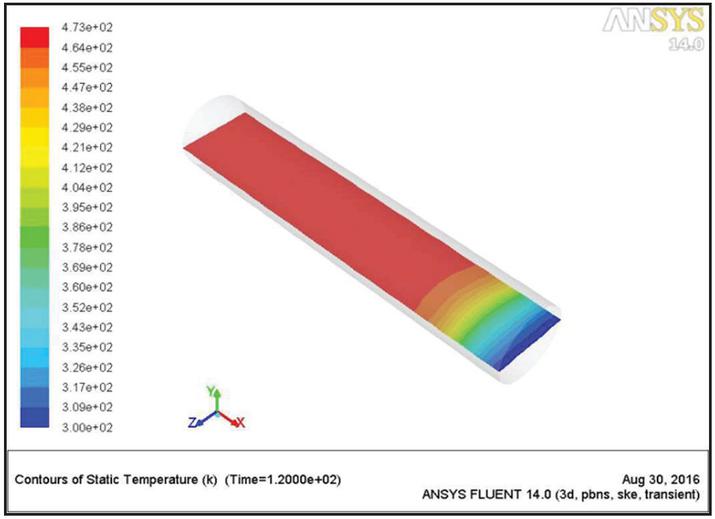
Figure 4 Temperature variation along regenerator length at plane y 0 for cooling cycle at t 2 min.
Both Figures 5 and 6 exhibit the length of the temperature contours of the regenerator bed throughout the course of the whole heating and cooling cycle, with the plane y 0. Serving as the reference point, which is the point at which steady state, or the point at which the pace at which heating and cooling occur is now constant, has been reached due to the solids’ absorption of heat energy The temperature of the input flue gases when they entered the regenerator during the heating cycle bed reduced, and it increased during the cooling cycle because of the heat energy that is emitted by the solids and the liquids. transmitted to the surrounding air.
The temperature change in simulated air and flue gas throughout a heating and cooling cycle is shown in Figures 7 and 8 respectively. The heating cycle is when the The temperature of the Flow of flue gas to the particles that make up the regenerator bed, resulting in a decrease in flue gas temperature as it passes through the regenerator. The heating cycle is interrupted after 60 seconds of heating, and a cycle of air intake for the cooling process the at 300 k in the other direction, the regeneration process begins.
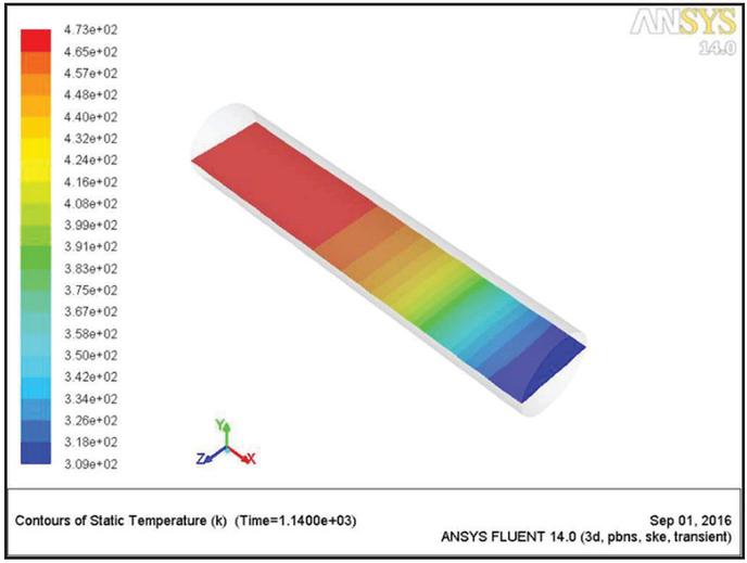
Figure 5 Temperature variation along regenerator length at plane y 0 for heating cycle at t 19 min.
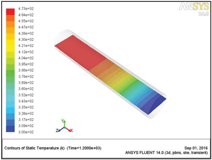
Figure 6 Temperature variation along regenerator length at plane y 0 for cooling cycle at t 20 min.
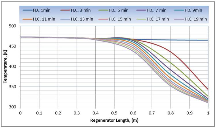
Figure 7 Variation of temperature with regenerator length during heating cycle.

Figure 8 Variation of temperature with regenerator length during cooling cycle.
5 Conclusion
The following is a list of the thermal attributes of the regenerator: follows: investigated, as well as the effects of other variables including height of the regenerator, the D/dp ratio, and the porosity. Ansys Fluent was used to study the pressure and temperature contours for regenerators of various lengths.
To explore the temperature change over the regenerator length, simulations of the regenerator were run in Fluent. The efficacy of the Using the outcomes of simulations to establish the exit flue gas temperature, the Depending on the temperature at which the regenerator operates, flue gas exited the system.
Finally, the Transient Computational Fluid Dynamics models for regenerators using D/dp 15 were developed and fluidly solved. The efficiency of each regenerator was calculated by looking at the simulation results for each iteration of the heating and cooling process. The transient model of this regenerator can be used in other thermal regenerator applications.
References
[1] K. Panwar and D. S. Murthy, “Analysis of Thermal Characteristics of the Ball Packed Thermal Regenerator”. Procedia Engineering, vol. 127, pp. 1118–1125, 2015.
[2] S. Ergun, “Fluid flow through packed columns”. Chemical Engineering Progress, vol. 48, pp. 89–94, 1952.
[3] R. E. Hicks, “Pressure Drop in packed bed of spheres”. Ind. Engg. Chem. Fund., vol. 09, pp. 500, 1970.
[4] D. Handly and P. J. Heggs, “Momentum and Heat Transfer Mechanism in regular shaped packings”, AICE. J., vol. 9, pp. 590–598, 1968.
[5] F. MacDonald, M. S. Ei-Sayed, K. Mow, F. A. L. Dullien, “Flow through porous media-Erguns equation revised”, Ind. Engg. Chem. Fund., vol. 18, pp. 199–208, 1979.
[6] B. Eisfeld and K. Schnitzlein, “The influence of confining walls on the pressure drop in packed beds”, Chemical Engineering Science, vol. 56, pp. 4321–4329, 2001.
[7] W. Reichelt, “ZurBerechnung des DruckverlusteseinphasigdurchstroKmter Kugel- und ZylinderschuKttungen”, Chemie-Ingenieur-Technik, vol. 44, pp. 1068–1071, 1972.
[8] K. Panwar, D. S. Murthy, H. P. Gangwar, R. Kumar, “ Comparative study of mathematical model and CFD simulation of a pebble bed heat regenerator”, International Journal of Scientific and Engineering Research, vol. 6, No. 4, pp. 1891–1896, 2015.
[9] K. Panwar and D. S. Murthy, “Analysis of Thermal Characteristics of the Ball Packed Thermal Regenerator”. Procedia Engineering, vol. 127, pp. 1118–1125, 2015.
[10] Panwar, K, Murthy, D, S, “Analysis of thermal characteristics of the ball packed thermal regenerator”, Procedia Engineering, 127, 1118–1125.
[11] Panwar, K, Murthy, D, S, “Design and evaluation of pebble bed regenerator with small particles” Materials Today, Proceeding, 3(10), 3784–3791.
[12] Bisht, N, Gope, P, C, Panwar, K, “Influence of crack offset distance on the interaction of multiple cracks on the same side in a rectangular plate”, Frattura ed IntegritàStrutturale” 9(32), 1–12.
[13] Panwar, K, Kesarwani, A, “Unsteady CFD Analysis of Regenerator”, International Journal of Scientific & Engineering Research, 7(12), 277–280.
[14] Singh, I., Bajpai, P. K., & Panwar, K. “Advances in Materials Engineering and Manufacturing Processes.
Journal of Graphic Era University, Vol. 11_1, 25–34.
doi: 10.13052/jgeu0975-1416.1112
© 2023 River Publishers